My workplace has an open floor plan with small desk/cubicles for everyone on the team, and with such a setup we all have a small plastic nameplate with our name and desk location on it. It is useful for facilities and such for understanding where a particular desk is, but doesn’t get much other use.
Well, a couple weeks ago I changed desk locations. That combined with my curiosity of E-Ink display for years now, and exactly how they worked, got me inspired. I decided to replace my boring paper nameplate, with something a little more custom. Below is my MVP (minimum viable product).

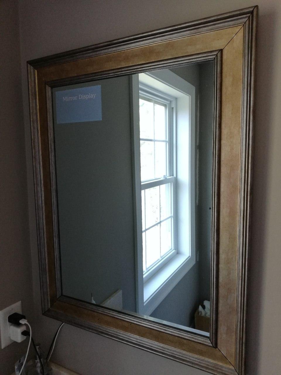
Old Nameplate 
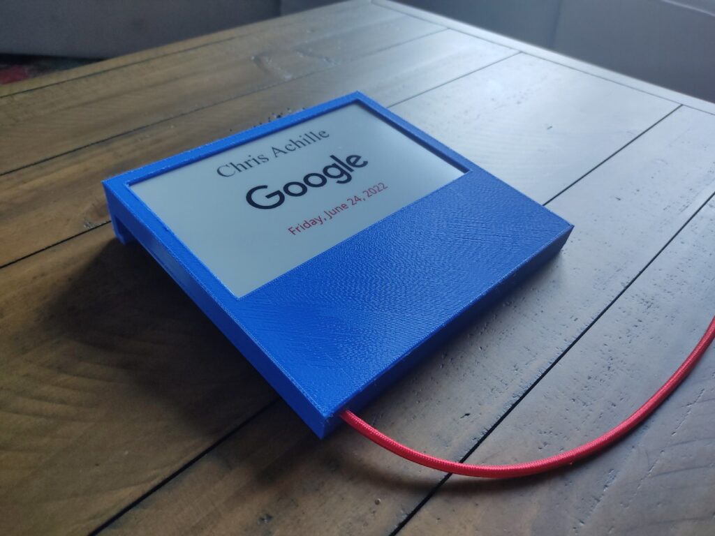
E-Ink Nameplate
Display
It all started with the display. After all, I have never played with one of these before and was curious to try it out. I found the Waveshare 7.5inch E-Paper E-Ink Display on Amazon, and decided to give it a shot. With some quick searches online I was able to discover that it had Raspberry Pi support, which was exactly what I was looking for.

I was pretty happy to see that this display supported red in addition to the basic black and white.
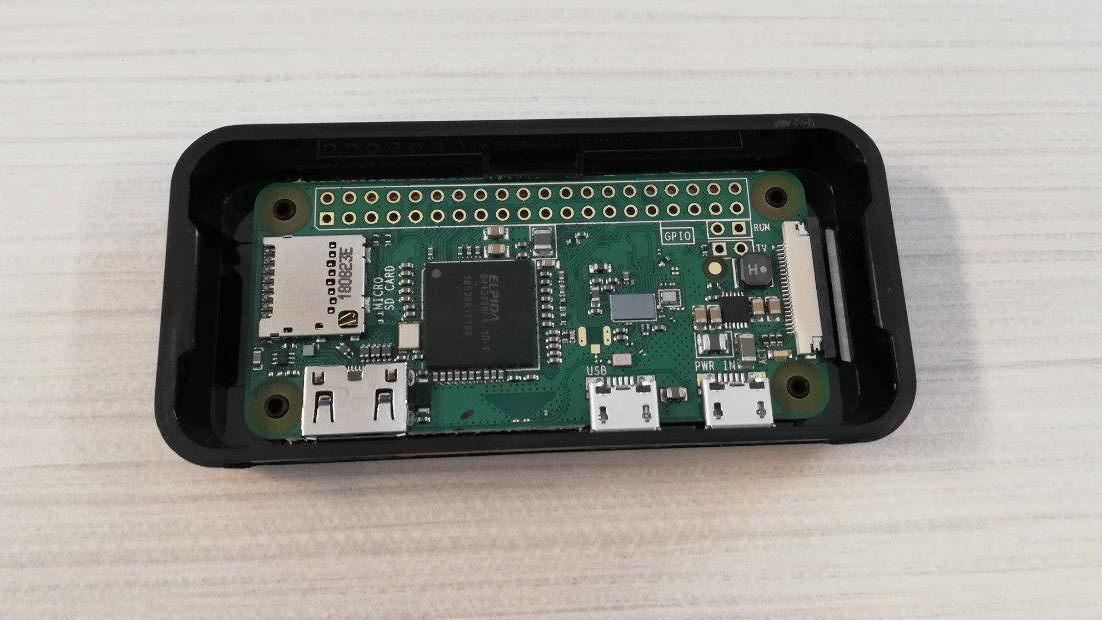
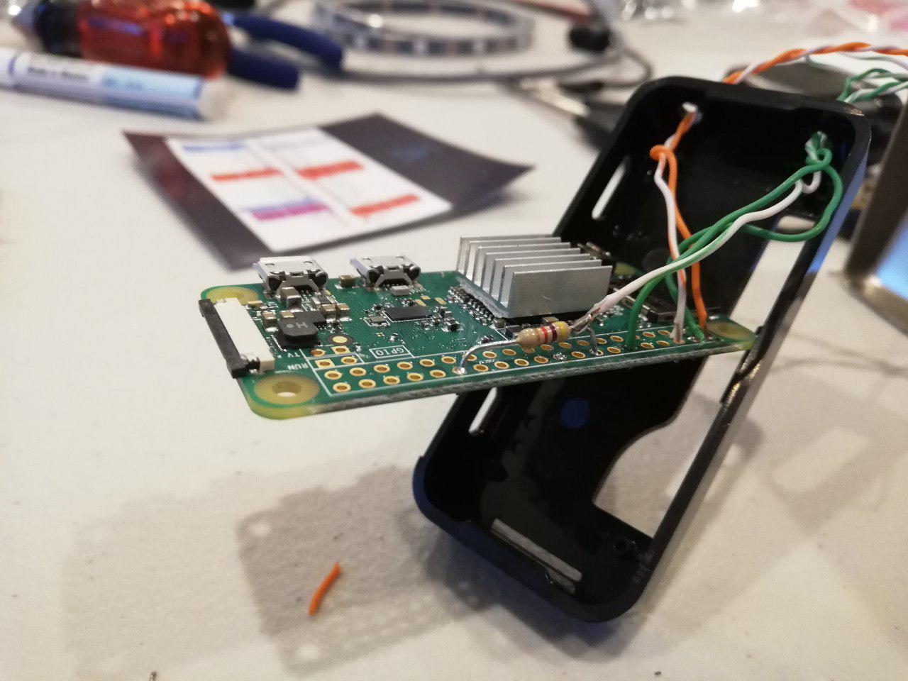
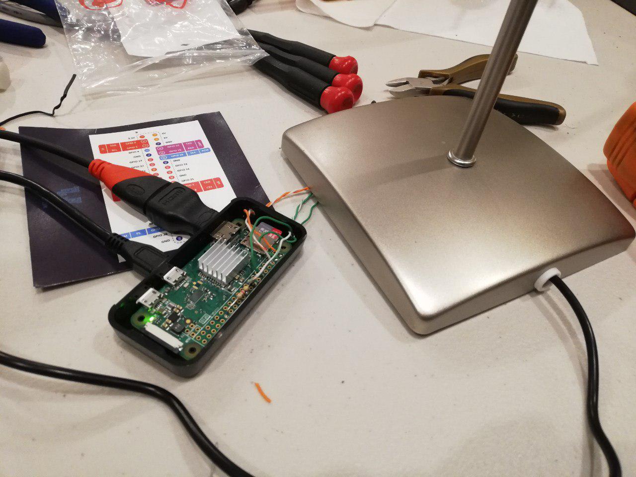
Raspberry Pi
After receiving the display, it only took about a night of playing with it and a spare Raspberry Pi I had sitting around to get it do some something interesting. I started with some of the sample code that they had, and made some small python modifications to print something pretty simple, with my name on it and the current date.
I could have went with something a lot more complicated (a mistake I have made many times before), but the point here was to really just prove it out, and to get a prototype working. So with that working, I was done with the application.
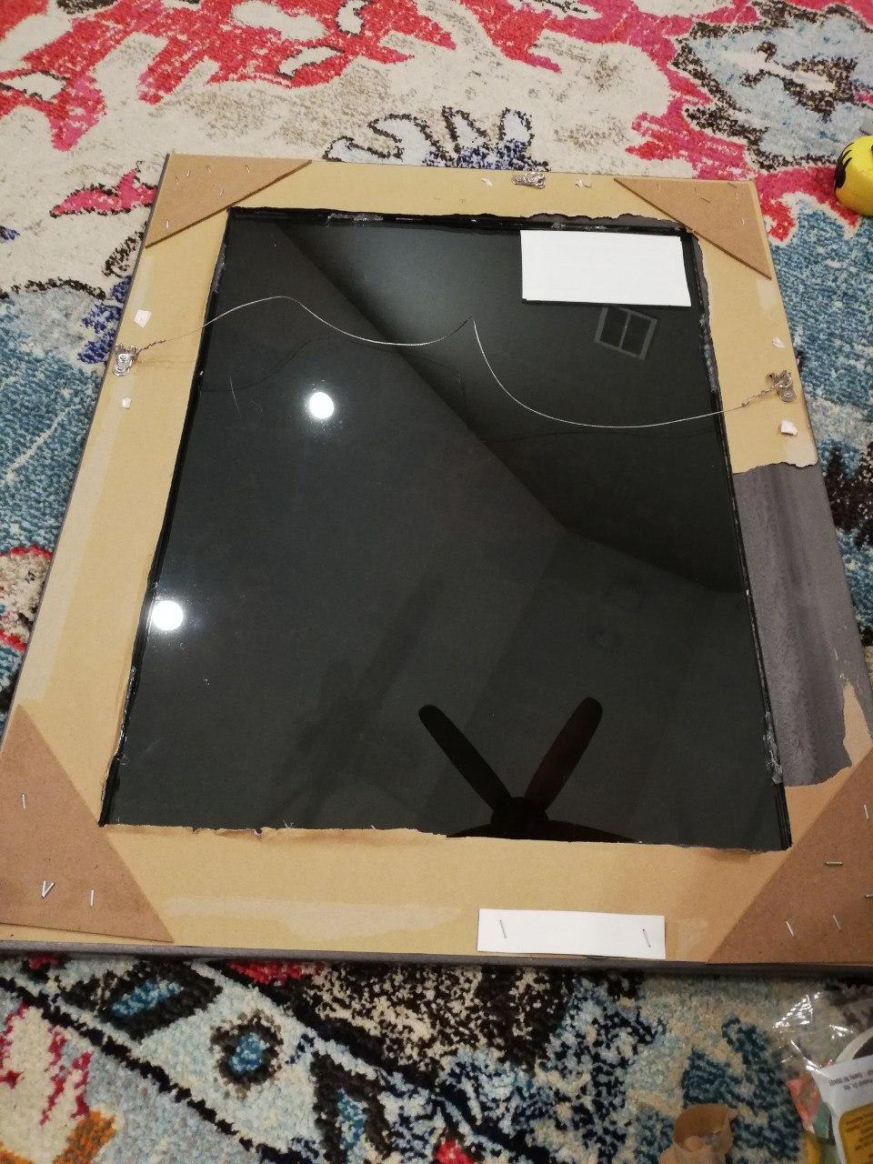
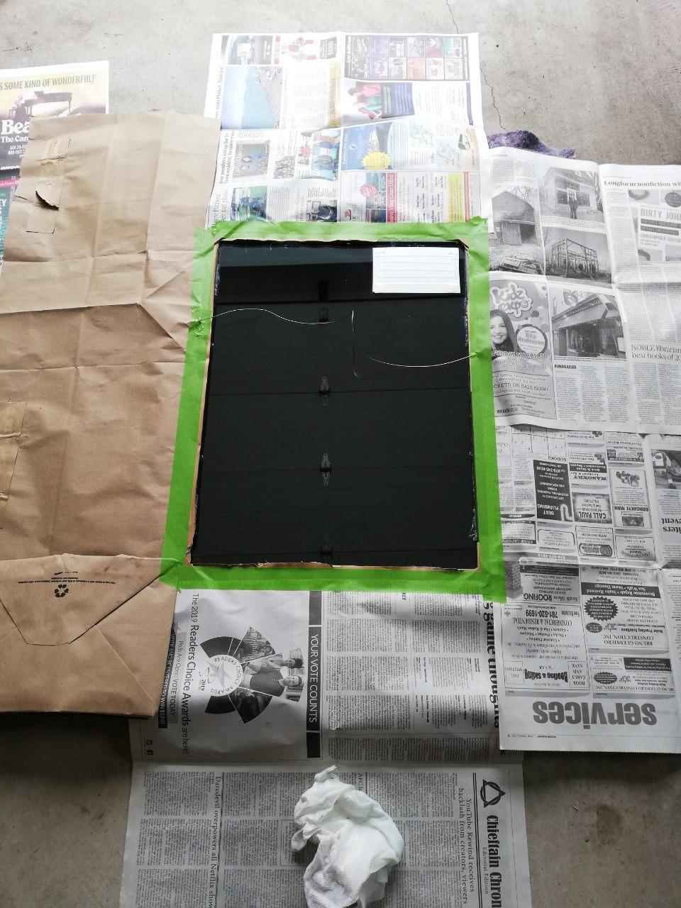
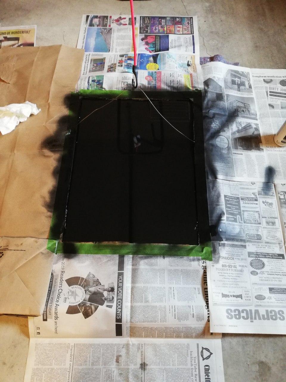
Case
My next task was to handle how I was going to display it. I originally thought something wood might be a good option, but I knew I just don’t have the skills to make something nice looking with any type of detail at all.
After thinking about it for a little while, I decided this would be a good opportunity to try another first…maybe I could 3-D print something? [Wait…wasn’t this supposed to be simple?] I had been wanting to print something simple from Thingiverse for a while, but I just have not gotten around to it, even though I have access to a 3-D printer.
Obviously nothing off the shelf is going to meet my exact needs, so I played around a little bit, and designed something using some custom measurements that I took, and also the specs from the display company. After a little bit of design, plugging it into the 3-D printer, and clearly some good luck, wallah, I had something that might actually work.

Printing in progress 
Printed back and front 
Back and front other sides
Final Construction
Taking the separate pieces, I put the display in the new case along with some good old epoxy to hold it in plate. I then added all the other components, added a USB cord to power it, and closed it on up (with some padding to hold other components in place).


Given that this is my first experience with E-Ink, and my first time 3-D Printing something, I am very happy with how it came out.
PS
Some lessons learned:
- When 3-D printing, the bottom of the print is the “rough side”, and should not be your presentation side. (In mine, I made it the front…ooops)
- Raspberry Pi’s are in extremely short supply right now (June 2022). A Raspberry Pi Zero W that you could have previously got for $10/$15 is now costing ~$80.